Hi all,
Getting two independent water tanks, one for either side of the house.
Up to 3 downpipes to feed into each tank.
Will need to be charged so I can run pipes underground to the tanks. maximum distance about 5m.
My problem is with a strainer at the downpipe, one of the tanks i'd like to get has very little excess head. In the image below 300mm head is recommended, i've seen 500mm in other diagrams. i probably have more like 100mm.
I'm not concerned about first flush, planning to have tankvac to get rid of any sediment that makes it in.
Water tanks are just for gardens so not soooo concerned about drinking quality for now.
Why is there the 300mm/500mm excess head usually recommended, what happens if i have 100mm head (as long as there is enough head to overcome the friction of the pipe).
Like ⋅ Add a comment ⋅ Pin to Ideaboard ⋅
WatchingStarredHistory
MembersPros
Browse Forums General Discussion Re: Water Tank Charged System Head 2Nov 04, 2021 4:46 pm Hi all, Getting two independent water tanks, one for either side of the house. Up to 3 downpipes to feed into each tank. Will need to be charged so I can run pipes underground to the tanks. maximum distance about 5m. My problem is with a strainer at the downpipe, one of the tanks i'd like to get has very little excess head. In the image below 300mm head is recommended, i've seen 500mm in other diagrams. i probably have more like 100mm. I'm not concerned about first flush, planning to have tankvac to get rid of any sediment that makes it in. Water tanks are just for gardens so not soooo concerned about drinking quality for now. Why is there the 300mm/500mm excess head usually recommended, what happens if i have 100mm head, or for arguments sake, no difference in head between bottom of strainer and inlet? Like ⋅ Add a comment ⋅ Pin to Ideaboard ⋅ Hi crazyaustrian One the regular posters on here goes by the name H20, is literally the guru of charged systems and rain water tanks. Maybe you can search for him and send him a private message cheers Simeon Architectural Homes & Duplexes - specialising in custom designing homes to your budget Get a Free Onsite Consultation Today or send a PM for information, questions or advice. 04 Nov 2021 8 Junior Member Re: Water Tank Charged System Head 3Nov 04, 2021 5:00 pm  Ashington Homes Ashington HomesHi all, Getting two independent water tanks, one for either side of the house. Up to 3 downpipes to feed into each tank. Will need to be charged so I can run pipes underground to the tanks. maximum distance about 5m. My problem is with a strainer at the downpipe, one of the tanks i'd like to get has very little excess head. In the image below 300mm head is recommended, i've seen 500mm in other diagrams. i probably have more like 100mm. I'm not concerned about first flush, planning to have tankvac to get rid of any sediment that makes it in. Water tanks are just for gardens so not soooo concerned about drinking quality for now. Why is there the 300mm/500mm excess head usually recommended, what happens if i have 100mm head, or for arguments sake, no difference in head between bottom of strainer and inlet? Like ⋅ Add a comment ⋅ Pin to Ideaboard ⋅ Hi crazyaustrian One the regular posters on here goes by the name H20, is literally the guru of charged systems and rain water tanks. Maybe you can search for him and send him a private message cheers Simeon yes i've been reading a few topics and noticed how good he is, was kind of hoping he'd pop up here. saveh2O Re: Water Tank Charged System Head 4Nov 05, 2021 5:19 am Ashington HomesHi all, Getting two independent water tanks, one for either side of the house. Up to 3 downpipes to feed into each tank. Will need to be charged so I can run pipes underground to the tanks. maximum distance about 5m. My problem is with a strainer at the downpipe, one of the tanks i'd like to get has very little excess head. In the image below 300mm head is recommended, i've seen 500mm in other diagrams. i probably have more like 100mm. I'm not concerned about first flush, planning to have tankvac to get rid of any sediment that makes it in. Water tanks are just for gardens so not soooo concerned about drinking quality for now. Why is there the 300mm/500mm excess head usually recommended, what happens if i have 100mm head, or for arguments sake, no difference in head between bottom of strainer and inlet? Like ⋅ Add a comment ⋅ Pin to Ideaboard ⋅ Hi crazyaustrian One the regular posters on here goes by the name H20, is literally the guru of charged systems and rain water tanks. Maybe you can search for him and send him a private message cheers Simeon yes i've been reading a few topics and noticed how good he is, was kind of hoping he'd pop up here. @h20 havent seen him post for a while. which is why I was thinking that maybe a PM might reach him as your question is rather technical. anyway, happy friday:) Architectural Homes & Duplexes - specialising in custom designing homes to your budget Get a Free Onsite Consultation Today or send a PM for information, questions or advice. Re: Water Tank Charged System Head 5Nov 05, 2021 3:16 pm My problem is with a strainer at the downpipe, one of the tanks i'd like to get has very little excess head. In the image below 300mm head is recommended, i've seen 500mm in other diagrams. i probably have more like 100mm. Why is there the 300mm/500mm excess head usually recommended, what happens if i have 100mm head (as long as there is enough head to overcome the friction of the pipe). Like ⋅ Add a comment ⋅ Pin to Ideaboard ⋅ I will go into some history and then post about some other endemic substandard practices and how to achieve Best Practice. It's better you grab a coffee and a sandwich I first saw the above diagram many years ago on a Victorian Plumbing Industry Commission (PIC) Technical Solution Sheet. I complained about the highly incompetent 'information' several times but nothing was done to right the wrongs. Years later, Technical Solution Sheet 0.01 was adopted when the PIC was abolished and combined with the former Victorian Building Commission to form the new Victorian Building Authority (VBA). In the interim and since then, the document and diagram has also been adopted by other State regulatory bodies and local councils. It still staggers me that with all the industry personell both at the coal face and in regulatory roles in various State bodies that this diagram and technical Solution Sheet was allowed for so long to promote its woefully incorrect information with negative consequences. My speaking to the VBA in recent years was also an exercise in futility. Several months ago the VBA finally decided during a clean up of all Technical Solution Sheets (now called Plumbing Solutions) to deem 0.01 obsolete and not replace it with competent advice or at the very least a correction. The amount of damage and endemic bad practices this widely promoted diagram has fostered is a disgrace. Why is it incompetent? 300mm head. The diagram clearly indicates that as long as you have a 300mm hydraulic head, you can have a wet system and this has been adopted as fact by numerous plumbers, tank installers and homeowners. This in turn has led to countless tanks overtopping during heavy rain. The required hydraulic head for a charged (wet) system must be hydraulically calculated to account for the roof area(s) harvested, the regions 1:20 Average Recurrence Interval (ARI), the pipe's true internal diameter, the pipe's length and the accounting of fittings such as tees and elbows as equivalent pipe lengths. The available head must be taken from the mid point above the vertical riser's top elbow's invert. Too many plumbers take it from this elbow's invert (water doesn't discharge paper thin during a high intensity rain event) and I also know of plumbers and others who have taken it from the tank's top inlet's mesh! The downpipe must also not be assumed to fill to the gutter's sole as downpipes drain by weir flow. There has to be a full column of water. Pipe. Plumbers are not hydraulic engineers but they should be able to do some simple calculations if trained in rainwater harvesting...which they are not! The commonly used 90mm pvc stormwater pipe is measured as an outside diameter,the commonly used SN2 pipe has an internal diameter (ID) of 86.2mm. While this doesn't sound like much of a difference, a true 90mm ID pipe holds almost 9.5% more volume than a 86.2mm ID pipe but this equates to about 13% more flow rate. It MUST NOT be calculated as a 90mm pipe, Using flimsy 90mm pvc stormwater pipe is not a good idea for rainwater harvesting wet (charged) systems. ARI. Eaves gutter roof drainage compliance is calculated by using a region's 1:20 ARI but the figure is the bare minimum qualifying figure, the reason I tell people to design the system with a minimum 20% safety margin. The diagram is also manifestly wrong in stating "Size of overflow equal to size of stormwater charge pipe" which is just ridiculous. A stormwater charge pipe flows full of water and could be servicing 3 or 4 or more downpipes plus there could be another downpipe at the tank whereas a horizontal discharge pipe draws a vortex and is also meshed! Horizontal drain pipes are also very inefficient. Of interest...a standard downpipe, unless flow restricted, will never contain less than 70% air. Up to 3 downpipes to feed into each tank. What region are you in and what is the roof areas harvested? You also need to make sure that the tanks won't overtop during heavy rain. There is a concerning trend towards fitting overflow outlets into the roof of dome topped tanks but this is usually bad design. Extra volume should never subjugate overflow capacity! An overflow pipe flows faster with more water above the pipe's horizontal invert or vertical crest. Most slimline tanks are also fitted with very high overflow pipes and little mitigation. A FEW THINGS TO KNOW... The overflow outlet's mesh presents a flow restriction but if you ask a plumber or even the tank manufacturer what the tank's overflow capacity is, they won't know! Now, how ridiculous is that? A vertical drain pipe is much more efficient than a horizontal drain pipe, for example, a 100mm ID horizontal pipe with 50mm and 100mm of water above its invert will flow at 1.34 [ps and 4.67 lps respectively whereas a same size vertical pipe with 50mm and 100mm of water above its crest will flow at 4.67 lps and 6.60 lps respectively but these figures are for unmeshed pipes! A 90mm pvc stormwater overflow pipe has an internal diameter of 86.2mm but the usual impervious coating on the mesh outer diameter further reduces the flow path to 84mm or less. A 90mm diameter round opening has a cross sectional area 15% larger than a 84mm cross sectional area. The overflow mesh must be accessible to avoid the need to remove the overflow pipe to clean the mesh but numerous tanks top meshed inlets are positioned without this consideration. To negate mesh maintenance and also increase the overflow's discharge capacity, you can fit a dual meshed air gap to the overflow pipe. These are a very, very good product. https://www.bunnings.com.au/rain-harves ... p_p4813647 You can also fit a flanged elbow inside the tank to have a more efficient vertical overflow intake but you must drill the hole lower than you normally would have if fitting a horizontal outlet. These fittings are sold by promoting their use to increase the tank's storage capacity BUT there must be sufficient water depth above the weir to ensure an adequate overflow capacity. https://rainharvesting.com.au/products/ ... h-flanged/ If you are on reactive soil, I also recommend fitting a swivel joint to the overflow pipe and vertical riser. My problem is with a strainer at the downpipe, one of the tanks i'd like to get has very little excess head. In the image below 300mm head is recommended, i've seen 500mm in other diagrams. i probably have more like 100mm. What shape tank are they and how high is the top meshed inflow located? What size are the pipes? If you have poly tanks, you can chase them on a subsurface sand base to also increase head. Fitting mosquito proof leaf diverters allows you to have a low restriction inlet. This gives you more minimum head and much more maximum head when the tank's water level is low because the head is then measured down to the water surface level in the tank opposed to the top of the vertical riser above the tank. It also lessens the height of water retained in the wet system's pipes and downpipes. A smaller low restriction inlet can branch off the charged carrier pipe near the vertical riser. Archaic rainwater harvesting methods deliver water to the top of a tank and have the pump draw water from the bottom of the tank. This causes sediment resuspension when water drops from a height and the pump also draws the worst quality water in the tank. Best practice delivers water to a valve above the bottom of the tank and has the pump draw the best quality water in the tank from near the top of the water surface. Like ⋅ Add a comment ⋅ Pin to Ideaboard ⋅ To draw water from a few hundred mm below the water surface, you need to attach a floating intake filter inside the tank to the pump's draw valve. It is simply a hose with a filter basket at the end which is attached to a buoy. We are prototyping our own at the moment and it will be different to the current copy cats on the market as it will have much finer filtration and also have some tricks I can't mention right now. Oh yes, it will also be cheaper. I'm not concerned about first flush, planning to have tankvac to get rid of any sediment that makes it in. Water tanks are just for gardens so not soooo concerned about drinking quality for now. First flush is the dirty roof wash, sediment is organic matter plus grit etc that is usually flushed during heavier rain. You should consider fitting DIY sediment traps just before the tanks to capture bed load. The design came about during our Supadiverta research and development program, readily adapt to any wet system and are very effective. Tank sediment build up will be minimal. Note that you need DWV pipe for the one in the diagram. We also use reducing invert tapers instead of the pipe reducer now. I do not recommend using flimsy 90mm PVC-u for charged piopes. The diagram was drawn by a H1 member, it is what was used on his system. Follow the link below to read his 12 month review. viewtopic.php?p=1146540#p1146540 Like ⋅ Add a comment ⋅ Pin to Ideaboard ⋅ To save heaps of money, you can easily make your own sediment vacuum system by optioning a very low 25mm or 32mm drain valve. At the time the valve is fitted to the tank, you attach a short length of flexible hose to the valve before it is lowered towards the hole. The hose will attach to a faucet tee (female fitting at the branch) and two pipes will also be fitted into the tee's sockets. The pvc pipe can be lightly bent with heat and the end of the pipes will be capped. The pipes will also have slots drilled towards the bottom but the total open area of the slots must not exceed x2 the pipe's cross sectional area. Slots are much more efficient then round holes and 4mm high slots are good when using leaf diverters. To operate, just open the drain valve whenever the tank is full and rain is expected. You need only flush for 30 seconds if you also have a sediment trap fitted.. 3in1 Supadiverta. Rainwater Harvesting Best Practice using syphonic drainage. Cleaner Neater Smarter Cheaper Supa Gutter Pumper. A low cost syphonic eaves gutter overflow solution. 04 Nov 2021 8 Junior Member Re: Water Tank Charged System Head 8Nov 07, 2021 5:54 pm Overtopping is the correct term for a tank spilling excess water through the top.meshed inlet to the ground. . Most punters call it overflowing but water overflows down the overflow pipe. Using two different terms hopefully reduces confusion and leaves no doubt as to what is being referred to. 3in1 Supadiverta. Rainwater Harvesting Best Practice using syphonic drainage. Cleaner Neater Smarter Cheaper Supa Gutter Pumper. A low cost syphonic eaves gutter overflow solution. 04 Nov 2021 8 Junior Member Re: Water Tank Charged System Head 10Nov 09, 2021 12:03 pm Like ⋅ Add a comment ⋅ Pin to Ideaboard ⋅ Like ⋅ Add a comment ⋅ Pin to Ideaboard ⋅ Like ⋅ Add a comment ⋅ Pin to Ideaboard ⋅ Like ⋅ Add a comment ⋅ Pin to Ideaboard ⋅ Like ⋅ Add a comment ⋅ Pin to Ideaboard ⋅ looks like id need additional overflow capacity in addition to the tankvac (540l/min capacity) on tank 1. Still working through linked forum, very useful as it explains a lot in basic terms to another user who was a rookie like me. So is my strategy to work out the length, elbow joins, friction losses in charged lines and ensure the current head can overcome the losses? or is that not the issue, as long as overflow capacity meets inflow capacity it shouldnt overflow? going to dig some pads this weekend which will help me determine how deep i can get these tanks down to help with head, i assume not much as i'll hit rock fairly quickly. Re: Water Tank Charged System Head 11Nov 10, 2021 8:42 pm So...the tanks are round with a flat roof. Is that right? I assume that they are poly. Good job with the numbers. The ARI is calculated by an area's average rain intensity over a 5 minute duration which is then transposed to a one hour figure which is a reference, not a reality. For example, a short duration heavy cloud burst could qualify as a 1:20 ARI whereas a longer period of less iintense but flooding rain will often fall well short. Have you ordered and optioned the tanks yet? The overflows can be optioned to attain a much higher discharge capacity, it's no stress. I assume you have planned at least one 100mm overflow pipe on each tank. Is that correct? When you measured the head at the leaf diverters, where did you assume the high point of the charged water column would be? I have an idea of how to (hopefully) solve the low head issue but I am worried as to where you have assumed the wet system's head will be. So is my strategy to work out the length, elbow joins, friction losses in charged lines and ensure the current head can overcome the losses? or is that not the issue, as long as overflow capacity meets inflow capacity it shouldnt overflow? The big problem is the inflow. If you had plumbed it without hydraulic consideration, the tanks possibly/probably may not have overflowed because not enough water would have flowed into them. Fortunately, you had the common sense to question the diagram, something that numerous plumbers have failed to do for year after year. Some of the installations I have seen have lacked all semblance of logical thought. Once I have the answer re where the wet system's assumed water column's apex is, I'll pass some thoughts by you. 3in1 Supadiverta. Rainwater Harvesting Best Practice using syphonic drainage. Cleaner Neater Smarter Cheaper Supa Gutter Pumper. A low cost syphonic eaves gutter overflow solution. 04 Nov 2021 8 Junior Member Re: Water Tank Charged System Head 12Nov 11, 2021 7:58 am They will be stainless steel tanks, with flat roofs. (rooves)? Have not ordered and optioned the tanks yet, so options open. I have stated the wrong thing in my pictures... those head heights are from the bottom of the elbow of the gutter to the top of the tank's flat roof. hmmmm Looks liked i'd lose another 266mm if measuring water column height at the leafeater/beater bottom. and I wouldnt have that hanging off the edge of the gutter... leaf eater would be much lower again. Like ⋅ Add a comment ⋅ Pin to Ideaboard ⋅ Like ⋅ Add a comment ⋅ Pin to Ideaboard ⋅ Think you suggested something like this? letting the inflow pipe reach down into the tank. why isn't this more commonly done? anything to be aware of? Like ⋅ Add a comment ⋅ Pin to Ideaboard ⋅ Re: Water Tank Charged System Head 13Nov 11, 2021 9:08 pm Think you suggested something like this? letting the inflow pipe reach down into the tank. why isn't this more commonly done? anything to be aware of? No, I wasn't suggesting a calming inlet, I was suggesting a low restriction inlet as per the photo I posted. "Low restriction inlet" is my given terminology because it services water from a less flow restrictive flow path, allowing the wet system to operate with more head. The method came about as a result of our extensive Supadiverta research and development program but it is also our now established best practice for any wet system provided they are fitted with mosquito proof leaf diverters. More later. First...a few notes about the diagram. CALMING INLET: These are a good idea BUT..... Having the vertical riser above the tank still limits the available head. A calming inlet must be used in conjunction with a mosquito proof leaf diverter. The diagram doesn't state this. There should also be a small vent hole drilled high up on the pipe but inside the tank to manage trapped air pockets iand to also prevent a syphon happening if the "inspection plug" at the bottom of the riser is opened. A calming inlet should rest on the floor, FLOATING INTAKE FILTER: Great idea but there are many sold that are not well thought out. There needs to be a disc or similar under the filter cage to support the basket above the sediment layer when the water level is low. A H1 member who took advice from this forum made his own, see thread linked below. BTW, he is also from Orange! viewtopic.php?f=35&t=97686 Many floating intake filters are sold with stainless steel filter baskets with 1,200 micron apertures that are designed for use in bores, dams and creeks/rivers. These are a useless unnecessary expense when water has already passed through 955 micron filter mesh at the top of the tank or when fitted to the current common leaf diverters. You cannot take the meshed filter off to clean and scrubbing the mesh (if there is anything to scrub) will only brush debris into the filter! The one in the photo below looks to have apertures finer than 1,200 micron but there is not enough distance between the top of the filter and the buoy. Like ⋅ Add a comment ⋅ Pin to Ideaboard ⋅ They will be stainless steel tanks, with flat roofs. (rooves)? Have not ordered and optioned the tanks yet, so options open. Roofs is an example of crass Americanisms that are forever crawling into our language but this one appears to have become entrenched.....like a cane toad! The Millennials however may see it change to RFs in the future along with all the other texting slang that continues to proliferate and pollute mainstream English language and communication. It is almost sacrilege to even partially bury stainless steel tanks. It's good that they haven't been ordered. I have stated the wrong thing in my pictures... those head heights are from the bottom of the elbow of the gutter to the top of the tank's flat roof. hmmmm Looks liked i'd lose another 266mm if measuring water column height at the leafeater/beater bottom. and I wouldnt have that hanging off the edge of the gutter... leaf eater would be much lower again. Can you borrow a laser level? Like ⋅ Add a comment ⋅ Pin to Ideaboard ⋅ The diagram above will (hopefully) be reoriented later, it won't paste in landscape for some reason. Please excuse my 'art' handiwork, it isn't my forte. If any reader out there can assist me with a better diagram, I would be most appreciative. The diagram shows a rainwater harvesting wet system with a low restriction inlet diverting off the vertical riser to a low inlet valve. NOTE: Water must first pass through mosquito proof mesh before entering a water tank. In most situations, it would usually divert from a DWV reducing junction fitted to the subsurface carrier pipe to provide a more fluid flow path. A low restriction inlet MUST be used with leaf diverters. Apart from you probably needing to include this in your design, it is also best practice that has the following benefits. The hydraulic head is measured to the water level in the tank. Low water levels = more head. The low inlet will always have more head than the top of the vertical riser above the tank. The low inlet supplements (boosts) the flow rate during heavy rain. The low inlet has priority flow. The water retained in the wet system we be the same level as the water in the tank, not to the height of water at the top of the vertical riser as per usual with archaic systems. The diagram also shows a vertical overflow intake inside the tank. Note the air gap fitted to the overflow pipe which allows the removal of flow restricting mesh at the tank's overflow outlet. The following figures are from AS 3500.1 and are for unmeshed outlets. The figures are in litres per second with different water levels above a horizontal outlet's invert (the bottom of the pipe) and above a vertical pipe's crest (weir perimeter. Both pipes are 100mm. Water height: (mm) 50 75 100 125 150 175 Horizontal:outlet 1.34 2.78 4.67 5.72 6.60 7.38 Vertical intake drain 4.67 5.72 6.60 7.38 8.06 8.73 FACT: An external overflow pipe has plenty of reserve volume due to it being occupied by an air core. To boost an overflow pipe's carrying capacity without eating into the tank's mitigation cacity, connect two overflow outlets to a single external overflow pipe. Like ⋅ Add a comment ⋅ Pin to Ideaboard ⋅ If you also fit the sediment trap design we use on our Supadiverta systems, you can also use it as an 'emergency' supplementary overflow. Air gaps need to be fitted to both external 100mm.overflow pipes. TANK 1 will need two 100mm vertical overflow outlets. TANK 2 will only need one 100mm vertical overflow outlet but it will require a small amount of mitigation above the 100mm vertical pipe inside the tank. The outlet holes must be drilled lower than what is required for a horizontal outlet. Where will the overflow pipes drain to? LEAF EATERS; These can leak from where they sit on the stormwater pipe but this is easy to prevent. The overflow point must be the bottom of the mesh. When calculating tank heights and the available head, still measure to the middle of the riser's horizontal pipe above the tank. Also, can the downpipes supplying tank 1 all connect to a single 150mm DWV pipe? The pipes at the top of the system can be 100mm DWV but then upsized to 150mm at the last 'filling station'. The connection at this point should be to 45 degree junctions to minimise turbulence. A single 125mm pipe has slightly more volume than two 100mm DVW pipes and less friction loss. For now, you need to consider the available head from the Leaf Eaters to the tanks (use a laser level if you can get one) and the size (and cost) of a low restriction inlet to fit to tank 1. The inlet would need to be fitted +200mm above the bottom of the tank at its lowest point. INTERESTING FACT: Pipes have increasing pressure losses along their length but each successive charge pipe acts as a water tower to 'repressurise' the carrier pipe where they communicate. 45 degree junctions should be fitted to minimise turbulence. The link below is a video that very simply demonstrates pressure loss along a pipe. https://www.youtube.com/watch?v=_hSL9_eo4n8 3in1 Supadiverta. Rainwater Harvesting Best Practice using syphonic drainage. Cleaner Neater Smarter Cheaper Supa Gutter Pumper. A low cost syphonic eaves gutter overflow solution. 04 Nov 2021 8 Junior Member Re: Water Tank Charged System Head 14Nov 23, 2021 1:36 pm 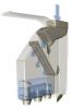 SaveH2O SaveH2OFLOATING INTAKE FILTER: Will decide if i go with these as i get closer to the date. Like ⋅ Add a comment ⋅ Pin to Ideaboard ⋅ This is great, I like it a lot more than my powerpoint presentation diagrams. The diagram shows a rainwater harvesting wet system with a low restriction inlet diverting off the vertical riser to a low inlet valve. What makes the low restriction inlet low restriction? simply because its at a lower down inlet point on the tank? Do you think i can get all my inflow points to a junction (from 4 100mm pipes coming from the roofs into a single 150mm pipe) then from there going into the tank through a vertical rise (still 150mm) and low restriction inlet (size)? The diagram also shows a vertical overflow intake inside the tank. Tank 1 - Tank vac plus 'normal' overflow (both 100mm diameter) will give me enough outflow capacity (tank vacs 540l/min plus the extra in second overflow through vertical intake). Can i still connect the 'normal' outlet to the tanks vacs outlet like this diagram? or i'll need two outlet pipes side by side (one tank vac, one 'normal'). Like ⋅ Add a comment ⋅ Pin to Ideaboard ⋅ If you also fit the sediment trap design we use on our Supadiverta systems, you can also use it as an 'emergency' supplementary overflow. does the supadiverta system replace a leaf diverter? and goes at the top of the gutter? Air gaps need to be fitted to both external 100mm.overflow pipes. Need for airgap on tankvac? TANK 1 will need two 100mm vertical overflow outlets. TANK 2 will only need one 100mm vertical overflow outlet but it will require a small amount of mitigation above the 100mm vertical pipe inside the tank. The outlet holes must be drilled lower than what is required for a horizontal outlet. so two 100mm outlet holes, how far down are we talking? I would have put right on the edge of the side, as far up as possible. Where will the overflow pipes drain to? Thinking to just let overflows into a rock pit to stop the water scouring away at soil and then down the hill from there onto a paddock. LEAF EATERS; Yes i will find someone with a laser level or just hire one for the day. Once i have prepped my concrete pad (hopefully at ground level or very slightly above) and have measurements to the bottom of leaf diverters(supadiverters??) will better understand the head of the system. Can the superdiverta system be used instead of leaf eaters? then i get sediment trapping as an added bonus right at the action at the start of the system. Because i have so many pipes feeding into the inlet can't see how to incorporate DIY sediment trap into the thing. https://www.youtube.com/watch?v=_hSL9_eo4n8 great watch thanks! 10 week lead time on these tanks, so keen to configure and get an order in. just need to finalise where what sized holes are going. Bit going on here, hope my questions and diagrams makes some sense.. Pretty sure I understand you, you've been making perfect sense =D At the moment what i understand: -Normal inlet on top, which will have mosquito mesh on it, don't have it shown in diagram, but two pipes from either end of the shed will also feed into this. dry system, not charged. Do i need leaf eaters on these edges? or the inlet on the top of the tank with mesh and mosquito mesh can be my leaf diverter... -Two 100mm overflow holes on the side of the tank (not right at the top edge, some distance down). -One low restriction inlet (150mm??) as low as i can get it on the side of the tank (which will come of the vertical riser). Will this riser inlet and tankvac outflow interact if too close? tank vac trying to drain at 9 l/min sucking things out and low restriction inlet letting a lot of water in. cant think that it should?? Will configure something similar for tank 2. Like ⋅ Add a comment ⋅ Pin to Ideaboard ⋅ Like ⋅ Add a comment ⋅ Pin to Ideaboard ⋅ 04 Nov 2021 8 Junior Member Re: Water Tank Charged System Head 16Dec 11, 2021 10:05 pm Sorry for the late reply, I didn't see your post until earlier this week and I have been unavoidably delayed since then. I'll answer your queries in order without quoting because the Qs are within my last post unfortunately. I call it a low restriction inlet because it has a less restrictive straighter flow path with more head amd less pipe and fittings. It is very simple and super effective but can only be used if leaf diverters or our Supadivertas are fitted. Re 3 DPs supplying a 150mm pipe & low restriction inlet, you are on the right track...I'll comment in detail later. Re Tankvac and 100mm overflow. The Tankvac would have to be fitted below the 100mm invert (bottom of pipe) which will reduce the tank's storage capacity. I have been experimenting with a simple, low cost DIY bottom syphon system that I will detail on our new website (coming soon) that people can fit to their tank at very low cost and have found the following during my research:
You also have to be aware of costs plus requirements to have rodent and mosquito proof mesh fitted to the tank's overflow outlet or pipe. I strongly suggest you don't fit mesh to the outllet for more than one reason! Next Q...see above answer. The Supadiverta has an internal 750mm 50 degree sloped filter but it is not suitable for your situation. Tankvac and air gap...yes. Don't try using a meshed tank outlet with a Tankvac but be aware of mandated rodent and mosquito proofing requirements for water storage tanks. TANK 1. 760 lpm during a minimum 1:20 ARI. Having leaf diverters allows you to divert directly into the tank. Do you know approximately the roof areas that each DP drains? IF hypothetically all DPs drained equal roof areas, each would drain 60 sq m and drain 152 lpm during a bare minimum 1:20 ARI. Two left DPs. A 104mm ID pipe flowing at 304 lpm has 0.35 meters of friction loss over 100m but you need to design for more than 304 lpm. Regardless, offsetting this is the fact that there isn't 100 metres of pipe and the DP nearest the tank recharges the carrier pipe at that station (important to use a 45 degree junction) plus the flow rate between the upstream leaf diverter and the downstream one is slower (less friction loss) than the section of pipe between the downstream leaf diverter and the tank. If this pipe diverted to a 100mm inlet at the top of the tank's wall, am I correct in assuming that you woud have an additional 150mm of head? Also, approximately how long is the ground level pipe? It is easy enough for me to add the fittings' friction losses as equivalent pipe lengths plus the riser etc and do calculations if I know the other lengths and roof areas. Like ⋅ Add a comment ⋅ Pin to Ideaboard ⋅ https://www.nationalpump.com.au/calculators/friction-loss-calculator/ Three right DPs. This pipe run needs a more accurate calculation but our hypothetical calculations denote 456 lpm during a minimum 1:20 ARI. The DP nearest the tank is very close and 456 lpm is a velocity of 0.9 metres per second but you need to design for more flow than this. If I know the distance between the DPs and the approximate area of each roof area, I can do some quick calculations. Upsizing to 150mm pipe before the DP closest to the tank will be vital. The 150mm SN4 has an ID of 151.6mm. We'll do some calcs and then look at a low restriction inlet. You will need two unmeshed 100mm high flanged overflow outlets connecting to a single 100mm DWV vertical overflow pipe but have the holes drilled lower than usual so that there is a bare minimum 100mm above the vertical pipes intakes. https://www.bunnings.com.au/rain-harves ... w_p4760110 TANK 2. 355 lpm during minimum 1:20 ARI. Having leaf diverters allows you to divert directly into the tank. It looks like you can plumb the corner DP as a dry system and have the other two DPs converge at a 100mm 88 degree junction (tee) and then a bend (elbow) at the bottom of a riser which either diverts to the tank's top meshed inlet or to a 100mm inlet at the top of the tank's wall. This would be the same level os the overflow and so there would be no reduction in storage capacity.. A single 100mm unmeshed overflow with a high intake elbow will suffice but have the hole drilled lower than usual so that there is a bare minimum 100mm above the vertical pipe's intake. https://www.bunnings.com.au/rain-harves ... w_p4760110 Holes for high flanged outlets...the top of the intake (crest) will be about the level of the bottom of a horizontal outlet. These fittings are foolishly promoted to increase a tank's storage capacity but done so by not warning consumers about the need to ensure that the tank's overflow capacity is not severely compromised. https://rainharvesting.com.au/products/ ... xtra-high/ Leaf Eaters are not essential for a dry system. Inform the tank dealer about using high flanged overflows. If considerig (or needing) a 150mm low inlet, it is best to ask the manufacturer and also get prices plus ask about availability of flexible hose. It would be the ideal solution. Tankvac's outet is at the top and it responds to the water level. The 80mm pipe diverts into a larger pipe and the syphon breaks at that point. Don't be fooled that it cleans the entire floor, a pool vac is the go. Also see previous comments about Tankvac. My DIY sediment trap design is very effective at removing bed load from the carrier pipe, It is far more effective to improive the water quality in the wet system by reducing as much muck as possible from entering the tank. 3in1 Supadiverta. Rainwater Harvesting Best Practice using syphonic drainage. Cleaner Neater Smarter Cheaper Supa Gutter Pumper. A low cost syphonic eaves gutter overflow solution. 04 Nov 2021 8 Junior Member Re: Water Tank Charged System Head 17Dec 17, 2021 8:08 am I really appreciate your replies and i'm even slower than you in getting back! So i've dug and measured my pad heights and have exact measurements of fall etc. keen to post and update and hopefully nail down and configuration. 03 Apr 2023 5 VIC Junior Member Re: Water Tank Charged System Head 18Apr 03, 2023 6:01 pm Thanks everyone, I just had some questions about charged systems, found this page and seems I will end with a whole trade qualification from here. Excellent information from people who know what they are talking about! Cheers. Aspiring builder trying to focus on doing the right thing! There must be such a thing as a good builder that I have not found yet! Trying to create it then! 04 Jul 2022 4 New Poster Re: Water Tank Charged System Head 19Apr 10, 2023 8:44 am SaveH2ORe Tankvac and 100mm overflow. The Tankvac would have to be fitted below the 100mm invert (bottom of pipe) which will reduce the tank's storage capacity. I have been experimenting with a simple, low cost DIY bottom syphon system that I will detail on our new website (coming soon) that people can fit to their tank at very low cost Have you had a chance to finalise the cheap, DIY bottom syphon system? I'm keen to start experimenting but might not need to if someone has already perfected it Re: Water Tank Charged System Head 20Apr 16, 2023 6:04 pm Unfortunately, the new website has been substantially delayed but the DIY tank vacuum system to be included is a simple DIY solution that uses low cost off the shelf fittings that I can detail here. The figures below may need refining after testing is resumed. Note that this method will not give the tank a total clean but it will clean the strategic areas chosen. 1. A drain hole needs to be drilled close to the bottom of the tank. The hole size will depend on the tank's size and height, the tank's floor area and the length of the vacuum pipes. A large tank will require a longer length drainpipe with a larger diameter. 2. There are YouTube videos that show how to lower a tank's outlet fitting into the tank and work it through the hole. The difference will be that you will also need to attach a short flexible hose to the fitting and attach the other end of the hose to a tee's branch. It is usually best to use a faucet tee (female thread in the tee's branch) but there are various options you can explore. Alternatively, you can plumb a single straight suction pipe but with a branch pipe that suctions the area around the tank's outlet that supplies the pump. 3. You must also connect pipes to the tee's two sockets and to do this, you usually need to connect one of the pipes to the tee once the tee is inside the tank. You can mark the pipe and the tee with pencil lines to ensure that the pipe joins the tee at the correct position. PVC pressure pipe can be curved a little by applying heat with a heat gun. Don't let the heat sit on one spot, keep it moving to avoid the pipe being burnt and keep it away from the ends. You must have the pipes shaped beforehand for obvious reasons and for equally obvious reasons, the end of the pipes must be capped but you can drill a hole in each cap. 4. Calculate the cross-sectional area of the pipe you are using and try to buy class 9 or class 6 pressure pipe because they have larger internal diameters than class 12 pressure pipe. 5. Drill 8mm holes at 4:30 and 7:30 o’clock. The 90-degree angle between the holes is considered optimal. You can also drill some 8mm holes in the tee. The cross-sectional area of an 8mm hole is 50.3mm. For larger tanks where a larger drainpipe is used, the holes furthest away from the drain outlet need to be increasingly larger. If all the holes in the pipe are the same size, the water and sediment closest to the pipe's outlet will be drawn towards the pipe more quickly than the water and sediment further away from the outlet. 6. The velocity through the holes must be between 0.5 m/s and 1.0 m/s. This flow velocity is high enough to effectively draw sediment towards the vacuuming pipe, but not so high that it causes excessive water turbulence and wastage. It also allows the total cross-sectional area of the holes to be up to 1.3 times the drainpipe’s cross-sectional area. This is known as the Open Area Ratio. 7. Open the drain valve when the tank is nearly full and rain is expected. You should not need to open the drain valve for more than 40 seconds or else close it once the discharge water is clear. A higher water level will produce greater discharge flow rates but coversely, the higher the water level is, the greater the flow rate required to effectively draw sediment towards the pipe. This is because an outlet draws water from above, the reason for the formation of free surface vortices in some other situations. 3in1 Supadiverta. Rainwater Harvesting Best Practice using syphonic drainage. Cleaner Neater Smarter Cheaper Supa Gutter Pumper. A low cost syphonic eaves gutter overflow solution. If you can calculate the reasonable charged head from let's say 100mm below the gutter to the top of where the vertical riser's horizontal discharge pipe will be, that… 11 17953 Once you know the basics, the rest is easy. Read my post in the thread linked below. viewtopic.php?p=1919271#p1919271 2 20408 Building Standards; Getting It Right! Thank you for the generous offer. I need to get the plumber out to give me an explanation. As mentioned I haven't seen any rain water discharge from pipes 1& 3. It… 7 11292 |