Hi all,
We have 2 water tanks on our property. 1 big concrete one that is fed by and supplies the main house. A second smaller poly sitting approx 1m lower is fed from and supplies our cottage. Now there are a number of problems I need to solve eg. there are less overflows than inlets and the big tank overflows into the little one so in heavy falls it doesn't stand a chance.
Now I tried to create what I though was a simple way to create a buffer of capacity in the little tank by linking a 32mm 'balance pipe' to the big one. As the little one is always full and the big one mostly empty after a very dry 6 months I though I could 'steal' 5000L out of the little one without having to use the cottage pump. The attached drawing shows what I have attempted to do, all the new and existing poly pipe is 32mm.
Now 2 things don't happen as I had envisaged. Firstly I open the ball valve to get the water to balance and very little or nothing appears to transfer, even when I turned off the pumps and left it all night. Secondly when I open this ball valve the main house pump really doesn't like it. It seems to pump water ok but when the pressure switch turns the pump off it sounds like water is gushing back out. It tries to start up again and makes some horrible noises so I don't push my luck and turn it off.
Everyone I have spoken to feels the levels should balance so maybe I'm not talking to people knowledgeable enough.
Like ⋅ Add a comment ⋅ Pin to Ideaboard ⋅
WatchingStarredHistory
MembersPros
Browse Forums General Discussion 08 Aug 2013 12 VIC Junior Member Re: Linking 2 water tanks, why doesn't this work? 8Mar 11, 2014 4:18 pm Let's get back to basics. Gravity flow will only stop (or slow down) if... 1. There is limited hydraulic head. 2. There is an obstruction. 3. The pipe's friction losses are excessive. 4. There is an air pocket, either partial or total. If there is an air pocket, the required air flushing velocity is a minimum of .8 metres per second. You state that you have fitted 32 mm poly pipe, this will be either metric or rural. Rural: This is measured as an inside diameter (ID). It has a lower pressure rating (usually 600 kPa or 800 kPa) than metric poly pipe. Metric poly pipe (Blue Line) is measured as an outside diameter (OD) and the ID varies with its wall thickness. The higher the pressure rating, the thicker the wall thickness and the smaller the ID. I do not know which poly pipe you are using and so for this example, I will use a 32 mm ID. The internal volume per metre of 32 mm ID pipe is .804 litres. A minimum flushing velocity of .8 metres per second is therefore .643 litres per second or 38.6 litres per minute. You have a very simple flow path and the hydraulic head is measured from one tank's water level to the other tank's level. The balance line flow path will however be subject to friction loss when flowing at the required flushing velocity of 38.6 litres per minute. The friction losses are calculated by having the inline fittings and elbows etc added to the pipe's length as equivalent lengths of additional pipe length. This can easily double the actual pipe length. It is easy to calculate the required hydraulic head needed to generate the required flow rate through a pipe once the total friction losses measured as total pipe length has been calculated. If the hydraulic head cannot generate the required flow velocity, then the line will not flush. 32 mm ID pipe can generate high flow rates with little head, for example, a 20 metre (total friction loss) length of pipe with a 150 roughness co-efficient needs 470 mm hydraulic head to generate your required air flushing velocity of .8 metres per second. There are two locations where there could be air pockets in the line. Now 2 things don't happen as I had envisaged. Secondly when I open this ball valve the main house pump really doesn't like it. It seems to pump water ok but when the pressure switch turns the pump off it sounds like water is gushing back out. It tries to start up again and makes some horrible noises so I don't push my luck and turn it off. The concern I have from the above is the mention of water gushing back out from the pump. This indicates that the pump is installed higher than the current water level in the tank it draws from and that there is no one way valve installed further down the pipe work. The pump MUST remain flooded. Having a check valve fitted downstream is a priority. The mention of "horrible noises" indicates cavitation. If so, this will destroy your pump. I strongly assume that the outlet valve on the large tank is closed when you use the house pump to draw from the smaller tank. If it isn't, then the 200 mm head in the big tank is insufficient to prevent a vortex forming. Now 2 things don't happen as I had envisaged. Firstly I open the ball valve to get the water to balance and very little or nothing appears to transfer, even when I turned off the pumps and left it all night. As per already posted. EDIT: Have a play with this very simple flow rate calculator. The 140 roughness coefficient already entered is close enough for the poly pipe if it has undulations. http://www.calctool.org/CALC/eng/civil/hazen-williams_g 3in1 Supadiverta. Rainwater Harvesting Best Practice using syphonic drainage. Cleaner Neater Smarter Cheaper Supa Gutter Pumper. A low cost syphonic eaves gutter overflow solution. 20 Aug 2010 14 QLD Junior Member Re: Linking 2 water tanks, why doesn't this work? 9Mar 12, 2014 2:57 pm The pipe is 32mm metric blue line. I will check later when it gets dark with a self leveling laser but I am 100% that the small tank level is currently higher than the house pump. The big tank level may not be though? However the sound of water gushing back out happens regardless of whether the big tank outlet is open or closed. Also I'm sure it didn't happen when I did the first test after installing the balance pipe (with both valves open). I cannot see any evidence of a one way valve installed between the big tank and house pump. Would this be at the tank outlet or the pump inlet normally? Surely one way valves would need to be easily accessible and not buried in the ground. The ball valve on the main tank could not act as a one way valve at the same time, could it? Please explain cavitation, is this similar to the noise my espresso machine makes when I forget to fill it with water If I set a tap running and adjust the pressure switch so that the pump does not cut out could I open the small tank valve in an attempt to clear any air lock that may be in the system? Many thanks for your help. There is no rush with this now, we have had some good rain here in SE QLD so the big tank now has 400mm (or 8000L). However I am keen to bury the new pipework at some stage and also be prepared for next years drought. 20 Aug 2010 14 QLD Junior Member Re: Linking 2 water tanks, why doesn't this work? 10Mar 13, 2014 2:59 pm OK, last night I did some more testing and now I am really puzzled. I admit I am not a plumber but I did study engineering so I should be able to grasp the basics. This is however my first experience of water tanks and pumps. I went to the new ball valve (marked red in the diagram) and opened it slowly. I could hear water coming through from the small tank side. I know it was from this side because when I close the ball valve at the outlet it stopped. Which begs the question how this new balance pipe can be empty when it is entirely below the water level in both tanks? With the pump turned off I then set a sprinkler to run and increased the pressure on the pump slightly so that it ran continuously. I then powered the pump and it successfully pumped water with supply coming from both tanks and then I set it with supply from the small tank only. However with both scenarios as soon as I turn the pump off we get the old problem of water gushing back through the pump and I think the clunking noise I am getting are coming from the pressure switch. Still puzzled I opened the new ball valve (RED) which flooded the balance pipe. Closed it again and filled a watering can from the main house outside tap. Pump worked fine so I returned to the ball valve, opened it again and water came through again! So every time run the main house pump it takes water from the balance pipe but it does not re-fill under gravity even though the highest point of the balance pipe is 300mm lower than the water level in the main tank. It is like the Tee is acting as a non-return valve! So a non-return valve appears to be the solution (close to the pump I assume?). But I still cannot work out how that balance pipe can be empty and why I don't get the issue when running off the big tank only. I checked at the main tank outlet and there is a ball valve connected to a 1 1/4" to 32mm connector and then a 32mm elbow - nothing else. I previously exposed the pipe all the way to to the point where I inserted the new Tee and there is no valve buried. Stumped  http://i122.photobucket.com/albums/o260/acem8/WaterTankSetupv2_zpsb4cdfd55.jpg Re: Linking 2 water tanks, why doesn't this work? 11Mar 13, 2014 7:19 pm I'm a complete total newbie, novice etc. so no knowledge at all, but looking at the diagram, and knowing gravity is involved, wonder if the feed to the cottage pump comes into play? Is it possible that, as shown, being lower (physically) it is an easier path for the flow. Can it be cut off (valve) to test? Again, I may be barking up a very big wrong tree... Re: Linking 2 water tanks, why doesn't this work? 12Mar 14, 2014 12:10 am Two things stand out. 1. The gushing sound of water running back when you turn off the house pump. This then begs the question; "What replaces the water flowing from the pump and how does the pump start if it has no water in it"? 2. Both pumps are connected to the same line when the house pump draws water from the smaller tank. This means that the house pump is also drawing against the cottage pump. Not the best set up. The balance line should be separate. Is there any way that air can be entrained from the cottage pump? How low is the cottage pump? Please explain cavitation, Very simply put, cavitation is caused by a low pressure region in the water flow, often caused by an elbow fitted too close to the pump's suction side, generating low pressure vapour bubbles that implode inside the pump when they meet a boundary layer, usually the impeller, in a higher pressure area within the pump. In the example above, the elbow increases the velocity and the faster water flows, the lower its pressure. The volume of water increases substantially when it forms a low pressure vapour bubble. Cavitation is complex as is super cavitation that is subject to a lot of current research, particularly with submarines. The sound and other symptoms you have described sounds like entrained air is entering the pump. Cavitation and entrained air are related but different. One difference is that while entrained air bubbles also enlarge when they are inside the pump, their volume increase is much less than low pressure vapour bubbles. Symptoms of entrained air are loss of prime, noise and vibration. Air entrainment also results in less efficiency, corrosion and other possible pump damage. In some situations, the pump's impeller can also become air bound. EDIT: The pipe is 32mm metric blue line. This pipe has an internal diameter of 27mm and an internal volume of .573 litres per metre. Using a roughness co-efficient of 140 to allow for undulations, our example 20 metres of friction loss 27 mm ID pipe would need a 650 mm head to attain an air flushing velocity of .8 metres per second. 3in1 Supadiverta. Rainwater Harvesting Best Practice using syphonic drainage. Cleaner Neater Smarter Cheaper Supa Gutter Pumper. A low cost syphonic eaves gutter overflow solution. 20 Aug 2010 14 QLD Junior Member Re: Linking 2 water tanks, why doesn't this work? 13Mar 14, 2014 12:34 pm I did think that maybe the cottage pump may be causing it, the 2 pumps pulling against each other. Does a reduction in pressure on the inlet side of the pump cause the pressure switch to kick in? I tested it by switching off the cottage pump and closing the ball valve at that pump and it made no difference. The cottage pump is about 2m below the bottom of the small tank. The main house pump is approximately 1/3 the height up the big tank. The pipework running from the big tank to the house pump is around the base of the tank (not lower as shown in the diagram) So do I fit a non-return valve at the inlet to both pumps? How can I achieve what I want without connecting the 2 systems in some way - does it require a diverter? Re: Linking 2 water tanks, why doesn't this work? 14Mar 15, 2014 12:59 am Does a reduction in pressure on the inlet side of the pump cause the pressure switch to kick in? A pressure drop on the (inlet) suction side signals that the tank's water level is low. This will make the pump stop; it is a run dry protection feature of pressure switches. A pressure drop at the discharge indicates a demand, for example, a tap opening. This makes the pump start. The main house pump is approximately 1/3 the height up the big tank. So do I fit a non-return valve at the inlet to both pumps? If a pump isn't flooded, it needs to have a check valve fitted. The cottage pump is flooded and would not normally need a check valve, however, the house pump is now drawing from the same line. Without seeing the plumbing, I can't give an accurate assessment but I earlier thought that a situation might exist where the house pump would draw against the cottage pump. Given that the cottage pump is 2 m below the small tank and that you have 32 mm pipe, this is now unlikely as the tank's head should generate a flow rate that would exceed any flow demands. The house pump is not flooded at the big tank's lower water depths and it needs to have a check valve fitted on a flooded section of pipe. This must be before the balance line for obvious reasons. Re low water levels in tanks, I posted earlier that the pump's draw valve on the tank must have at least 200 mm of head to prevent a vortex forming. Many pump manufacturers recommend a 300 mm head. The head is from the TOP of the pump's draw valve to the tank's water level. Naturally, vortex formation varies as it depends on the suction velocity and the size of the outlet valve and the pipe. There is a formula for this but it is complicated. I can post it if needed. Given that you are using the water inside the house, is this for potable use? If so, then the pump's draw valve should not be fitted close to the bottom of the tank to prevent it drawing the worst quality water from the anaerobic zone. If the TOP of the valve is let's say only 130 mm above the bottom of the tank, your minimum water level should be no lower than 330 mm. IF the valve was sitting at the very bottom of the tank, then your minimum water level would still be close to 250 mm but having the valve at the very bottom is unthinkable. Without being on site, it is very difficult to give an opinion as the need to know the levels and pipe lengths is critical. The description of gushing water flowing from the house pump indicates that there is no check valve. Is it a self priming pump? Fitting a check valve would be my first step. 3in1 Supadiverta. Rainwater Harvesting Best Practice using syphonic drainage. Cleaner Neater Smarter Cheaper Supa Gutter Pumper. A low cost syphonic eaves gutter overflow solution. Re: Linking 2 water tanks, why doesn't this work? 15Mar 15, 2014 10:16 am Blue Line poly pipe. The link below shows a chart with the Blue Line specifications. http://www.polypipe.com.au/images/PE%20 ... nsions.pdf The nominal pipe size is shown in the LH column. Go along the top column until you get to SDR 13.6. This is the same pipe as PN 12.5 (not shown). PN 12.5 indicates a maximum pressure rating of 1,250 kPa. If you align the SDR 13.6 with 32 mm, you will see that the 32 mm (OD) Blue Line poly pipe has a minimum wall thickness of 2.4 mm and a mean ID of 27 mm. SDR indicates the ratio between the wall thickness and the OD. In other words, a lower SDR indicates a thicker wall, a smaller ID and a higher pressure rating. For the lay person, the PN rating is less confusing but the use of the SDR rating is increasing. The two specifications are often listed together, see table in the link below. http://www.polypipe.com.au/prod46.htm The choice of the pipe with the most appropriate pressure rating must allow for valve and solenoid closures as well as pump start ups that all produce pressure waves. The difference between the internal volume of metric and rural poly pipe is substantial. A 32 mm ID pipe has a volume of .804 L/metre. A 27 mm ID pipe has a volume of .573 L/metre. As per above, a 32 mm ID pipe has 40% more volume than a 32 mm OD pipe with a 27 mm ID. The pipe's ID is always used when doing flow rate calculations; never ever use the nominal size. 3in1 Supadiverta. Rainwater Harvesting Best Practice using syphonic drainage. Cleaner Neater Smarter Cheaper Supa Gutter Pumper. A low cost syphonic eaves gutter overflow solution. 20 Aug 2010 14 QLD Junior Member Re: Linking 2 water tanks, why doesn't this work? 16Mar 19, 2014 4:01 pm SOLVED!! Well kind of, I'm still not completely sure what was happening and neither could the experienced guy at the plumbing merchant. I previously posted that I thought the balance pipe was empty because I could hear water coming through as I opened up the small tank ball valve (BV2). However, if I close off BV5 situated after the main house pump (in the pressurised pipework) then it doesn't happen. So somehow the 10m of head pressure in the house pipework was feeding back into the small tank. Fitting a simple non-return valve as shown in the diagram below has stopped that happening and now I am able to run off both tanks at the same time or one at a time. I have also concluded there must be a non-return valve buried somewhere between the big tank outlet and the point where the balance pipe intersects. This would also explain why I am unable to balance the tanks. Also the 3-4m of head pressure above the cottage pump means the main house pump does not draw on the cottage pump. The cottage pump cannot draw on the main house pump because I have now installed the non-return valve. Question - can I leave BV3 permanently open and the main house pump will take from whichever tank has the higher water level? All pipe diameter are the same, the main tank has a slightly easier flow path but then the small one isn't complicated. http://i122.photobucket.com/albums/o260/acem8/WaterTankSetupv3_zpsbc4d911b.jpg Re: Linking 2 water tanks, why doesn't this work? 17Mar 19, 2014 5:35 pm Fitting a simple non-return valve as shown in the diagram below has stopped that happening and now I am able to run off both tanks at the same time or one at a time. 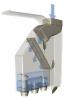 SaveH2O SaveH2OThe house pump is not flooded at the big tank's lower water depths and it needs to have a check valve fitted on a flooded section of pipe. This must be before the balance line for obvious reasons. I would have fitted the non return valve before the balance line so that you can transfer water between tanks. As is, you can only transfer from the smaller tank to the larger tank PROVIDED that there isn't a check valve already fitted somewhere near the larger tank (as I believe there is) that is already stopping water flowing from the smaller tank to the larger tank. With the new check valve fitted in the balance line, you will not be able to use it as a balance line although the house pump will be able to use the balance line to access the smaller tank. Also the 3-4m of head pressure above the cottage pump means the main house pump does not draw on the cottage pump. The cottage pump cannot draw on the main house pump because I have now installed the non-return valve. Correct...but the cottage pump also cannot draw from the big tank due to the new check valve. Question - can I leave BV3 permanently open and the main house pump will take from whichever tank has the higher water level? All pipe diameter are the same, the main tank has a slightly easier flow path but then the small one isn't complicated. The above is assuming that there is an 'unknown' check valve near the large tank that is stopping water flowing from the small tank to the larger tank. BV3 is redundant for any purpose other than to isolate the smaller tank from the house tank. Most water will be drawn from the tank with the greater head relative to the house pump, particularly during low flow demand. 3in1 Supadiverta. Rainwater Harvesting Best Practice using syphonic drainage. Cleaner Neater Smarter Cheaper Supa Gutter Pumper. A low cost syphonic eaves gutter overflow solution. 20 Aug 2010 14 QLD Junior Member Re: Linking 2 water tanks, why doesn't this work? 18Mar 20, 2014 12:54 pm I choose to put the non-return valve in the current position because it was easy to do for test purposes - it just screwed in to the ball valve BV3. I could move it to where you suggest but I have 2 reservations; 1) The position suggested would be 400mm below soil level and behind a bush which makes access in the future difficult. Are these valves service items that can go wrong? 2) After major rain events the level in the big tank will be higher than the overflow in the small tank. If BV4 is not closed I could slowly lose water from the big tank? 3) If the big tank ran out of water and we closed BV4 and then ran both properties off the small tank, is there a possibility of creating an air lock in the system if the small tank water level was below the suggested position of the non-return valve? ie. cottage pump pulls all the water out of the balance line. Re: Linking 2 water tanks, why doesn't this work? 19Mar 20, 2014 4:46 pm It is only an educated guess when one cannot see the topography. Some things suggested are not always feasible. At the moment and assuming that there is a check valve near the large tank that prevents water being transferred into that tank, the current set up only prevents water from being transferred between tanks. While having a facility to transfer water would be handy, it probably matters little to your situation as it is something that you can get around if needed. The big tank should not lose water if the new check valve does its job. Nevertheless, you would be wise to close BV3 whenever the house pump is not drawing from the smaller tank. I was concentrating on air pockets and air flushing rates because of earlier advice that there was not another check valve fitted near the bigger tank. You will not get entrained air or air pockets unless a tank outlet draws a vortex at a low water level. The air has to be infused. Provided the tanks water levels are sufficient, this won't happen. The unknown check valve was preventing water draining back from the house pump to the big tank but when you fitted the balance line, you created an unrestricted flow path to the smaller tank. Depending on the height of the water in the smaller tank in relation to the height of the house pump, air could/would have been ingested into the house pump when the height of the house pump and the smaller tank's water level reached equilibrium. The pump noises would have been a result of the pump trying to run with some air in the pump. It is strange as to why the pressure switch did not stop the pump when it detected low pressure. There has to be another check valve already fitted near the big tank that prevents water flowing back from the house pump to the big tank. If there isn't, then water would have been flowing back prior to creating the new flow path to the smaller tank. There being another check valve is evidenced by the fact that you are unable to transfer water from the smaller tank to the bigger tank. 3in1 Supadiverta. Rainwater Harvesting Best Practice using syphonic drainage. Cleaner Neater Smarter Cheaper Supa Gutter Pumper. A low cost syphonic eaves gutter overflow solution. Re: Linking 2 water tanks, why doesn't this work? 20Mar 21, 2014 9:58 am Is the smaller tank's outlet valve that supplies the pump(s) a 32 mm valve or do you have a 32 mm (27 mm ID) poly pipe connected to a 1" or even a 3/4" outlet valve? 3in1 Supadiverta. Rainwater Harvesting Best Practice using syphonic drainage. Cleaner Neater Smarter Cheaper Supa Gutter Pumper. A low cost syphonic eaves gutter overflow solution. That was always going to be a challenge and a test of patience. Full marks to your mate. Did you discuss the wet area near the trampoline? 16 18471 Hi All, I just wanted to close this topic out with an update. So we ended up agreeing to a number with the insurance company, and after an extensive amount of hand… 8 24835 |