I was wondering how the plumbing works to collect rainwater for a rainwater tank that we are planning on retrofitting after handover. Basically, the story is our architect has recommended we collect 80% of rainwater from the roof, and has "designed" our collection systems/downpipes that way.
My question is, if we decided to collect 100% of rainwater instead, will there be a problem if the design only caters for 80%? Is this something we should push at the planning stage or can it easily be fixed after handover?
Thanks!
WatchingStarredHistory
MembersPros
Browse Forums Eco Living Re: Rainwater tank design for retrofitting 2Jul 05, 2014 1:27 am  trixee trixeeMy question is, if we decided to collect 100% of rainwater instead, will there be a problem if the design only caters for 80%? Is this something we should push at the planning stage or can it easily be fixed after handover? When "designing" a rainwater harvesting system, the roof area harvested should be used to calculate the inflow during a 1:20 Intensity Frequency Duration (IFD) and the tank's overflow pipe sized so that the inflow does not exceed the tank's overflow capacity when the tank is full. Has the architect told you what the 80% roof harvest area is in square metres, the calculated flow rate during a 1:20 IFD for your region and what the overflow pipe's flow capacity will be? These figures will give you your basic design parameters. You also need to know whether a roof slope calculation was made to allow for wind driven rain to determine possible flow rates during a 1:20 IFD given that less than 100% of the roof plan area was intended to be harvested. The slope calculation should also be used to size the tank's overflow pipe when less than 100% of the roof is harvested. If the total roof area is harvested, you do the calculations off the roof plan area and not the slope factoring that is also used to determine gutter and downpipe size compliance. A % safety margin should also be factored to allow for storms with a intensity greater than a 1:20 IFD. 3in1 Supadiverta. Rainwater Harvesting Best Practice using syphonic drainage. Cleaner Neater Smarter Cheaper Supa Gutter Pumper. A low cost syphonic eaves gutter overflow solution. Re: Rainwater tank design for retrofitting 3Jul 05, 2014 2:22 am 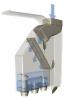 SaveH2O SaveH2OWhen "designing" a rainwater harvesting system, the roof area harvested should be used to calculate the inflow during a 1:20 Intensity Frequency Duration (IFD) and the tank's overflow pipe sized so that the inflow does not exceed the tank's overflow capacity when the tank is full. Thanks for your reply H2O, I've noted that you're a font of knowledge in this area! But I'm a complete noob and have some rather dumb questions: 1. What does 1:20 mean? 2. What happens if the inflow exceeds the tank's overflow capacity when full? I don't recall the architect mentioning any of this stuff, it was all designed on his perception of what we were likely to need in terms of usage. Thanks! Re: Rainwater tank design for retrofitting 4Jul 05, 2014 12:34 pm trixee1. What does 1:20 mean? A 1:20 IFD is a 1 in 20 year storm event. They use to be called a 1:20 Average Recurrence Interval and you may have read references to this. I have continued to refer to an ARI for continuity but have now switched to the IFD reference because ARI is being used less and less. A 1:20 IFD occurs more regularly than once every 20 years and localised intense storms are becoming more frequent. The 1:20 IFD is a measure of rainfall intensity over a 5 minute duration but it is expressed as mm/hr. For example, if your region's 1:20 IFD is 180 mm/hr, the 5 minute intensity is an average of 3 mm/min. To have a 1:20 IFD, you only need to have that 5 minute intensity. If you have eaves gutters, the maximum roof area drained by each downpipe is calculated by a formula that uses your region's 1:20 IFD and the chosen gutter and downpipe sizes. If you have box gutters, the formula uses a 1:100 IFD. A 1:100 IFD has an intensity that is about 50% greater than a 1:20 IFD. Remember when Melbourne and other areas flooded 3-4 years ago? That was caused by a 1:500 IFD. It was the intensity over the short duration that caused the flooding rather than prolonged rainfall of far less intensity. Let's say that you were harvesting 200 sq m of roof and your 1:20 IFD was 180 mm/hr (based on a 3 mm/min average rainfall intensity for 5 minutes), the tank would be receiving 200 x 3 = 600 litres per minute for that 5 minute duration if you experienced a 1:20 IFD (with no wind). If the roof area harvested was subjected to wind driven rain, then a greater amount of rain would be falling on that area of roof. When calculating gutter and downpipe sizes, the roof slope is factored to allow for this, for example, if a downpipe was serving a 30 sq m roof plan area and the roof had a standard 23 degree slope, then the roof area would be recalculated with a 1.21 multiplier, giving a factored roof area of 30 x 1.21 = 36.3 sq m. If there was no wind, the amount of rain falling on the roof would be 1 mm x 1 sq m = 1 litre. However, if the roof was subject to wind driven rain, then that area of roof would harvest more water while the roof area in the rain shadow would receive less. This is why the tank's overflow pipe(s) should have a flow capacity safety margin that allows for wind driven rain during an intense storm event. If the entire roof is harvested, then the roof plan area (no slope factoring) is used but a tank overflow capacity safety margin is still recommended to allow for the possibility of storms with an intensity greater than a 1:20 IFD. It should be noted that water tank installation regulations either don't recommend the above or else are poorly written. Compliance with poorly written or non existent regulations does not guarantee good design. Most people have water tank installations that are sub standard and often not compliant. trixee2. What happens if the inflow exceeds the tank's overflow capacity when full? The tank will over top. Apart from washing away garden beds and possibly annoying neighbours, concentrated flooding next to the slab can contribute to slab heave if the slab is on reactive soil. When the drought broke in SE QLD, I was contacted by numerous home owners who had tanks installed as per the mandate of the Brisbane City Council that required the tank to harvest 100 sq m of roof or 50% of the roof area, whichever was the greater but the mandate (written by bureaucrats) gave no reference to the tank's required overflow capacity. The Brisbane 1:20 IFD is about 4 mm/min for the 5 minute intensity duration and when they had heavy rains, the tanks over topped. It is easy to design a good rainwater harvesting system that accounts for the tank's overflow capacity but there are many other common mistakes that you also need to avoid. 3in1 Supadiverta. Rainwater Harvesting Best Practice using syphonic drainage. Cleaner Neater Smarter Cheaper Supa Gutter Pumper. A low cost syphonic eaves gutter overflow solution. Re: Rainwater tank design for retrofitting 5Jul 05, 2014 7:18 pm Thanks H20! I find I'm having to read your post carefully because it introduces terminology I'm not familiar with, but I think I get it now. I did a quick google for the 1:20 IFD and noted from some of your other posts that in Perth it would be 2.5mm per minute over 5 minutes, or 150mm/hr. I think we will be having mostly eaves gutters, with box gutters around the garage. However I don't know what the pipe sizes will be. Should I speak to the builder's plumber to find out? Our total roof area is 294 sqm, so in my situation that would be 735 litres/minute, and 80% of that is 588L/m. I think possibly I need to take a step back, as we're planning on installing the tank after handover ourselves. But we want to make sure the plumbing will be OK in that no major rework will need to be done. So the question is really whether the catchment area (whether 80% or 100%) needs to be designed in now, or can we specify 80% now and change it to 100% later when we get around to actually installing the tank? Thanks again for your help! Re: Rainwater tank design for retrofitting 6Jul 05, 2014 9:59 pm trixeeOur total roof area is 294 sqm, so in my situation that would be 735 litres/minute, and 80% of that is 588L/m. A single tank would require two 100 mm overflow pipes. If you had only one 90 mm overflow pipe and the tank was full, it would struggle with heavy rain of .9 mm/minute when harvesting 80% of the roof (294 x .9 x .8 = 212 lpm). trixeeI think we will be having mostly eaves gutters, with box gutters around the garage. However I don't know what the pipe sizes will be. Should I speak to the builder's plumber to find out? The eaves gutter cross sectional area and the downpipe size is determined by the roof area harvested and the 1:20 IFD. The respective sizes will be calculated by the architect. I went to your blog and noticed that you prefer the ½ round gutters. This style has the best efficiency and flushing characteristic and is a good choice but the downpipe will almost certainly be 90 mm round PVC as I don't think that 100 mm round will fit this profile. This will restrict the roof area drained to each downpipe to a slope factored area of about 45 sq m. As I don't know the roof slope and the gutter's cross sectional area, I can only give an estimate that this equates to a roof plan area of about 37 sq m maximum. This in turn means an absolute minimum of 8 downpipes but there will be at least 9 and possibly 10. As I don't know the roof area drained by the box gutter, I have made the above observation based on there being no box gutter so as to simplify the explanation. trixee So the question is really whether the catchment area (whether 80% or 100%) needs to be designed in now, or can we specify 80% now and change it to 100% later when we get around to actually installing the tank? Designing for an 80% roof harvest area can only mean the tank's overflow capacity, I can't see any other meaning. As far as the tank goes, it is only a matter of having 2 overflow pipes for an 80% roof harvest area. If the total roof area was harvested, you would need 3 x 100 mm overflow pipes. An extra pipe (or two) can connect to a single vertical pipe because overflow pipes never fill with water unless there is an obstruction. The photo below shows how two overflow pipes can share the one vertical pipe. The third taller pipe in the photo is a wet system vertical riser. The architect may be referring to the house plumbing and usage but rainfall patterns are unpredictable. Houses are usually finished with the downpipes connected to a stormwater system but I understand that in WA, they often simply run to ground or soak wells for ground water recharge. If it is not difficult to connect the downpipes after you move in, you just need to connect the downpipes to a couple of 100 mm DWV pipes and divert to the tank. This is much easier and cheaper than having stormwater pipes laid and everything then redone as you would in most other areas. My only concern would be if you were firstly required to have several large soak wells and then having some of those become redundant when the downpipes are later diverted to the tank. This would be a wasted expense. Have you asked your architect? Your blog mentions perhaps up-sizing to a larger 22,000 litre tank. This is wise if you are in an area that has a dry period of several months and you harvest a reasonable catchment area. Larger tanks don't cost all that much more but they are higher unless you have the room for a squat tank. If you are on any sort of slope and can position the tank on the down slope, that's fine but if you can't, you need to know whether you will have sufficient head between the gutter and the tank's top inlet to generate the required flow rate to prevent water backing up during a storm. Also, don't forget the height of the tank's slab when doing the calculations. The diverted pipes will also be buried and the downpipes will remain partially full of water and so they have to be round PVC. Your architect will know this. You are also much better off having the modified wet system that I have mentioned in other threads but I can repeat the design here if needed. It is a simple adaptation. Standard wet systems are archaic, sub standard and something that you really don't want. You have mentioned Josh Byrne's rainwater harvesting system in your blog, that system falls in the archaic category. Also, get your architect to explain your options with mains water switching devices. I can also explain them here if need be. You could also do a forum search for "mains water switching device". Check back before optioning the tank too. Most tanks are poorly optioned and this can cause a lot of trouble. If you are having a submersible pump, it is important that you check back before it is plumbed. Other considerations depend on the end use. Do you anticipate potable usage? 3in1 Supadiverta. Rainwater Harvesting Best Practice using syphonic drainage. Cleaner Neater Smarter Cheaper Supa Gutter Pumper. A low cost syphonic eaves gutter overflow solution. Re: Rainwater tank design for retrofitting 7Jul 06, 2014 11:47 am Thanks again H2O. We have 2 soakwells specced at the moment, one at the front and one at the back. Is the modified wet system you're talking about, the one in this thread: http://forum.homeone.com.au/viewtopic.php?f=35&t=59393 ? I'll have to go back through the thread and make some notes. With the mains water switching system, we were planning on using the one that detects the water level in the tank, and when it gets too low it will automatically switch to mains. We do anticipate potable usage, in fact this will be the main usage. Reasoning is that the garden will get enough water from winter rains in winter and most of its requirements from the greywater system in summer. Using the rainwater in the house seems to be the best way of maximising the rainwater usage. Re: Rainwater tank design for retrofitting 8Jul 06, 2014 1:42 pm trixee We have 2 soakwells specced at the moment, one at the front and one at the back. They will have to be big soakwells. Is this with having no tank and will this need to change when you get a tank? trixee Is the modified wet system you're talking about, the one in this thread: http://forum.homeone.com.au/viewtopic.php?f=35&t=59393 ? Have a look at this thread... viewtopic.php?f=35&t=60317 The system had to evolve because of complications with the tanks but it turned out for the better I think. The OP has also given a 12 month summary and there are several diagrams and other associated matters discussed. trixee With the mains water switching system, we were planning on using the one that detects the water level in the tank, and when it gets too low it will automatically switch to mains. That describes an automatic mains water switching device. There are also bullet proof cheaper manual systems available but it is common for people not to be told of their options or the failings of powered automatic devices. Have a read of this Whirlpool thread, one of many. http://forums.whirlpool.net.au/forum-re ... ?t=2154752 trixee We do anticipate potable usage, in fact this will be the main usage. The secret is to deliver the best quality water possible to the tank and then supply the best quality water in the tank to the filters to give them an easy life. The thread that I have already linked discusses an easy way to keep the wet system clean but you might also consider having first flush diverters. One problem with first flush diverters is that they reduce the yield. If you can use the diverted flush, then all the good but it is something to think about. Have a look at this overflow system. http://www.tankvac.co.nz/ Don't be confused by the short overflow pipe, it is a 900 mm length 80 mm internal diameter DWV pipe that drains into a larger pipe to break the syphonic vacuum. If you had this in conjunction with an appropriate tank mitigation level above the overflow outlet, this would be all the overflow that you would need plus it draws the worst quality water and sediment from the anaerobic zone. It is available in Australia. Whatever you do, don't let the tank supplier fit the tank with a low fitted outlet (less than 80 mm above the bottom of the tank at the valve's lowest point) that supplies the pump unless you are using a float device like the WaterBoy. http://www.crystalclearwater.com.au/waterboy/ Leaf diverters are also essential when using a wet system. These are discussed (and used) in the system discussed in the linked thread. A settling tank system is best when you harvest rainwater for potable use. This generally entails diverting to a large settling tank that is at a height that enables it to gravity divert to a smaller but tall tank at or near the house. If you have just the one tank and the water level is low, the concentrated flow of water falling into a tank from a wet system pipe can result in sediment re-suspension but being on mains means that if the tank's water level is low, you can simply switch over to mains water for a few days. trixee Reasoning is that the garden will get enough water from winter rains in winter and most of its requirements from the greywater system in summer. You might be interested to read this report... http://www.ata.org.au/wp-content/upload ... _final.pdf 3in1 Supadiverta. Rainwater Harvesting Best Practice using syphonic drainage. Cleaner Neater Smarter Cheaper Supa Gutter Pumper. A low cost syphonic eaves gutter overflow solution. Re: Rainwater tank design for retrofitting 9Jul 06, 2014 5:53 pm SaveH2O Is this with having no tank and will this need to change when you get a tank? This is a question I will need to ask of the architect, as they kind of glossed over this. SaveH2OHave a look at this thread... viewtopic.php?f=35&t=60317 The system had to evolve because of complications with the tanks but it turned out for the better I think. The OP has also given a 12 month summary and there are several diagrams and other associated matters discussed. Thanks for that, I have that one bookmarked. However I'm not sure how much of it applies as my system will be simpler with just one tank, and it will be close to the house. SaveH2OThat describes an automatic mains water switching device. There are also bullet proof cheaper manual systems available but it is common for people not to be told of their options or the failings of powered automatic devices. Have a read of this Whirlpool thread, one of many. Ouch! I hadn't considered switch failure either :/ SaveH2OHave a look at this overflow system. http://www.tankvac.co.nz/ Don't be confused by the short overflow pipe, it is a 900 mm length 80 mm internal diameter DWV pipe that drains into a larger pipe to break the syphonic vacuum. If you had this in conjunction with an appropriate tank mitigation level above the overflow outlet, this would be all the overflow that you would need plus it draws the worst quality water and sediment from the anaerobic zone. It is available in Australia. That sounds promising! All other points noted. I clearly need to do more research, I didn't realise there were so many variables involved. SaveH2OYou might be interested to read this report... http://www.ata.org.au/wp-content/upload ... _final.pdf Now that's what I call interesting! Good to know, I've been wondering about this but good information on this topic is so difficult to find, a lot of it seems to be made up. Re: Rainwater tank design for retrofitting 10Jul 06, 2014 7:28 pm trixee SaveH2OHave a look at this thread... viewtopic.php?f=35&t=60317 The system had to evolve because of complications with the tanks but it turned out for the better I think. The OP has also given a 12 month summary and there are several diagrams and other associated matters discussed. Thanks for that, I have that one bookmarked. However I'm not sure how much of it applies as my system will be simpler with just one tank, and it will be close to the house. Just look at the diagrams of the sediment trap and the low restriction inlet. Don't worry that the low restriction inlets are on a dedicated flush/outdoor tank. The problem with standard wet systems is that they have a vertical riser that needs a lot of velocity to transfer solids to the meshed inlet at the top of the tank. To put it in perspective, a horizontal drain pipe is recognised as needing a minimum flushing velocity of .7 metres per second and you will need two 100 mm PVC DWV (drain waste vent) pipes to transfer water from your downpipes to the top of your tank. You will have two SN6 DWV pipes and these have an internal diameter of 104.2 mm, giving a volume per metre of 8.53 litres. 8.53 litres per metre x .7 metres per second x 60 seconds per minute = 358 litres per minute each pipe. As you can see, a lot of the debris in the horizontal wet system pipes will have no hope of being flushed up a vertical riser on your system, even during a 1:20 IFD given that a vertical riser requires a greater flushing velocity than the horizontal flushing example that we have used. Fitting a small branch pipe off each 100 mm pipe fitting at the base of the riser and diverting each smaller pipe to let's say a 40 mm inlet fitted a minimum of 100 mm above the bottom of the tank at the inlets lowest point and within 75 degrees of the pump's draw valve will provide a higher velocity low restriction (flatter) flow path into the tank that allows the wet system to be flushed every rain event. Unlike standard wet systems that accumulate sediment and require periodic flushing, your wet system pipes would only retain the cleanest water that comes off the roof at the end of each rain event. Microbial breakdown of organic matter depletes the water of oxygen, hence the term anaerobic. Unlike debris trapped in an enclosed pipe, debris that finds its way into a tank is in water that can breathe. Because the low restriction flow paths will operate with greater head pressure than the vertical risers due to the height difference between the variable height of the water level in the tank and the top of the vertical risers, most of the water will flow at higher velocity through the low restriction flow paths unless you have heavy rain. Water flowing into a tank at a low level also oxygenates the anaerobic zone. It is ironic that nearly all rainwater harvesting systems divert water to the top of the tank and draw water from the bottom anaerobic zone, the opposite of what is best. If you also fit a DIY sediment trap to a non turbulent section of horizontal pipe, you will also capture practically all of the bed load (settled particulates) and the tank will have minimal sediment build up. Water diverted into a tank has to pass through mosquito proof mesh, therefore leaf diverters would have to be fitted to each downpipe if you have low restriction inlets. Fitting leaf diverters reduces the available head but this can be compensated by the additional flow through a low restriction flow path. The available head has to be factored in the hydraulic flow calculation when determining the best size for a low restriction inlet. These simple things will make it easier on the pump and filters, improve the stored water quality and increase yield by not having to regularly flush the wet system. 3in1 Supadiverta. Rainwater Harvesting Best Practice using syphonic drainage. Cleaner Neater Smarter Cheaper Supa Gutter Pumper. A low cost syphonic eaves gutter overflow solution. Re: Rainwater tank design for retrofitting 11Jul 07, 2014 4:27 pm Thanks for that H20. I'm going to go away and do a bit more research and write up my results so I get it clear in my head, will report back to this thread so others can benefit. I have one last question though regarding water pressure. In WA our outlets (e.g. showerhead) are "restricted" to I think 9L per minute (though there are exceptions). What is the water pressure from a rainwater tank like? Is it likely to be lower than this? Re: Rainwater tank design for retrofitting 12Jul 07, 2014 8:37 pm trixeeI'm going to go away and do a bit more research and write up my results so I get it clear in my head, will report back to this thread so others can benefit. I love it when people say this. A lot of others read the various threads and your consideration of others is admirable. trixeeIn WA our outlets (e.g. showerhead) are "restricted" to I think 9L per minute (though there are exceptions). What is the water pressure from a rainwater tank like? Is it likely to be lower than this? Good question but a proper answer about pumps and pressures has to consider several variables. You have more study coming up! I try to explain things the best I can rather than just give answers so hold on. The mains water pressure delivered to a house is now mandated at a maximum of 500 kPa. Many houses are less than this and it can be as low as 400 kPa, sometimes even less. This may sound like a big drop but it isn't what it seems because you need four times the head pressure to double the flow rate through a same sized pipe and so a 20% reduction below the permitted maximum is no drama provided the house plumbing has been correctly calculated for hydraulic friction losses. Pumps selected for household use usually deliver a pressure of between 200-400 kPa, the pump size depends on the use. I need to add here that while doubling the flow rate through a same size pipe needs four times the head, a pump needs eight times more energy. This is because there is more friction loss the faster the water flows and this is important to understand. When you look at a pump's specifications, it will show the Watts, head and flow rates etc but this is what the pump delivers from the pump, not what is delivered to the fixture. The specifications however usually also show a flow curve and this shows the reduced flow rates at various head losses. http://www.onga.com.au/objectlibrary/33 ... rmance.pdf By way of example, if you turn on a garden tap and fill a bucket, the bucket will fill a lot faster than if you attached a 12 mm garden hose to the tap and then filled the bucket. The reduced flow rate is a result of friction losses and the flow is referred to as dynamic head. Pressurised water in the pipes that isn't flowing is referred to as static head, that is, it will be the same pressure throughout the pipes as the delivery head. When you have a dual water system, you need to have the pump installed for efficiency. If the pump has further to pump the water to the house or to the most disadvantaged fixture, the higher the friction losses will be. The pump's location where it connects to the house needs to consider this for best efficiency. The shower is limited to 9 lpm by a flow restricter but this can be removed if necessary. Cisterns are mandated to fill at not less than 6 lpm and low flows are not a problem. It should be noted that many cisterns are still fitted with cistern valve seals that are designed for the older higher mains water pressures. Some cistern valves have an optional lower pressure valve seal and the popular and very compact Fluidmaster 400UK063 cistern valve has two optional lower pressure seals available. http://www.haron.com.au/fluidmaster_products.html Washing machines also fill slowly. If the pump will also supply a separate garden tap, the supply pipe must not be small. Also, rainwater is naturally acidic and copper pipe should not be used. Rather than use a 12 mm garden hose for watering, use an 18 mm hose but connect a short length of 12 mm hose to the end so that you can still use the standard garden fittings. At 20 lpm, the 18 mm hose has about 8 times less friction loss. The thread below discusses friction losses to a tap supplied by a powerful pump. Although hidden, there is no doubt that the plumber used small diameter pipe between the pump and the tap. viewtopic.php?f=35&t=61588 You will need time to choose the best pump for your needs. Most people are sold a big pump but you need to consider the following: A pump's start up energy demand is often 3-4 times the run demand. If you have a big pump supplying a lot of pressure (higher potential flow rate) to a low flow demand fixture, the pump is operating inefficiently. A big pump's start up mode can cause water hammer when supplying a washing machine. A pump's life span relates to the number of start/stops and its operational mode. If a tap is turned on only briefly, the pump will start. You can buy pumps that have variable speed drives and soft starts. Grundfos is one well known brand. This makes the pump much more energy efficient ($$$ savings) and also results in considerably less wear and tear but the pumps are expensive. You can also have a pressure tank fitted. Pressure tanks (sometimes called accumulators) have an internal bladder or diaphragm that pressurises the water that is pumped into the tank by the pump. A large stand alone (located away from the pump) pressure tank will supply about 35% of its capacity before the pump starts and refills the tank. For example, a 100 litre pressure tank would deliver about 35 litres of water. The pump starts and recharges the tank before it empties. Less noise. The pump operates at its peak efficiency when recharging a pressure tank as opposed to being choked when supplying low flow fixtures. Less energy is used. The pump will have an easier and much longer life. The bladder absorbs water hammer. The pressure tank can be located away from the pump, for example, you can have the pump at the water tank and the pressure tank at the best location to connect to the house. One disadvantage is that the pressure fluctuates as the tank empties. The tanks do come with different pressure settings but they can be adjusted. Bigger tanks take longer to drain and so the fluctuation is not as noticeable. The pump's pressure switch cut in/cut out settings must be compatible with the tank's pressure setting. For example, if you had a tank set at 28 psi (as mine is), the cut in/cut out pressures on the pump's pressure switch would be 30/50 psi. 1 psi = 6.9 kPa. The links below explain how pressure tanks work. http://irrigationrepair.com/how_pressur ... _work.html http://www.apswater.com/article.asp?id= ... e_problems Pump selection is important and I hope that this has been of help. 3in1 Supadiverta. Rainwater Harvesting Best Practice using syphonic drainage. Cleaner Neater Smarter Cheaper Supa Gutter Pumper. A low cost syphonic eaves gutter overflow solution. Re: Rainwater tank design for retrofitting 13Jul 14, 2014 7:25 pm Just posting to let you know that I'm still here and haven't forgotten to post. I haven't had as much time to research as I'd like so am slowly getting there. Having said that, I'm now up to 10 pages of notes and am still finding tangents, so will have to do some ruthless editing first! Re: Rainwater tank design for retrofitting 14Jul 15, 2014 4:29 am That's fine. It sounds like you have understood a lot of the information. It's mostly common sense and easy once you're on a roll. You will soon be helping others. 3in1 Supadiverta. Rainwater Harvesting Best Practice using syphonic drainage. Cleaner Neater Smarter Cheaper Supa Gutter Pumper. A low cost syphonic eaves gutter overflow solution. Re: Rainwater tank design for retrofitting 15Jan 18, 2015 1:35 pm I'm back! At our first prestart with the builder yesterday, we addressed the rainwater situation. Points of note:
Re: Rainwater tank design for retrofitting 16Jan 18, 2015 3:44 pm I have just read through the thread to refresh my memory. It turned out to be a long coffee break but I am happy with the information given. I have designed a superior high yield no maintenance leaf diverter that I have decided to manufacture. I need to do field trials and then make the tooling plus do the legals etc (and find the time) and so it won't be available for a while unfortunately. The problem with the current designs are high yield losses and maintenance issues. The type that use a large aperture outer mesh (usually 6-8 mm) and a mosquito proof inner mesh let bird droppings and a lot of decomposing and finer organic material through the outer mesh where it will then either wash through to the tank or else block the inner mesh. To overcome these problems, some now use mosquito proof mesh on the outside but this can result in decomposing leaves sticking to the mesh and unacceptable yield losses. Just be aware that you will have maintenance issues but they are a must have when you have a wet system and mandatory if you have a low restriction inlet. If you have a TankVac tank overflow, make sure that the pipe isn't installed too high as it has a delayed prime and needs mitigation. It also has an 80 DWV outlet pipe, you need to make sure that a larger overflow outlet isn't fitted that will prevent a Tankvac from being fitted. You would need 2 x 100 mm overflow outlets if you don't have a Tankvac. Note that the Tankvac's smaller outside pipe drains into a larger standing pipe (usually 100 mm DWV) that also acts as a vacuum break. The standing section must be high enough to generate a charged flow capable of accepting the high volume syphonic inflow. If you have a settling tank system, the tank supplying the house should be closest to the house because of the pump. What have you decided about the pump? A variable speed pump will provide constant pressure rather than fluctuating pressure as you would have if you use a pressure tank. A variable speed pump is expensive but you will save on energy costs and the pump will have a long life. If you do use a pressure tank, don't have a 20/40 psi controller setting. 30/50 or 40/60 psi settings have less noticeable pressure fluctuations, something you need to consider for the shower. The thread that I have linked below discusses these issues in greater detail. I strongly suggest that you also read this thread. viewtopic.php?f=35&t=72564 I also recommend using a sediment trap in each underground pipe. These are easy to fit and will be of great benefit. You can fit the drain outlet so that you can collect and use the water. The Alternative Technology Association website has a harvested rainwater use calculator called the Tankulator. This allows for harvest yield losses due to evaporation, first flush losses etc and it would be worth your while to have a play with it as well. http://tankulator.ata.org.au/ 3in1 Supadiverta. Rainwater Harvesting Best Practice using syphonic drainage. Cleaner Neater Smarter Cheaper Supa Gutter Pumper. A low cost syphonic eaves gutter overflow solution. Re: Rainwater tank design for retrofitting 17Jan 19, 2015 11:15 pm Thanks for the great info, SaveH20! Good luck with your leaf diverter, it's a shame it won't be ready in time otherwise we'd be very interested. The guy we've organised a quote with is on holidays for a couple of weeks so it'll be a while before we get any info back. The TankVac sounds like a good idea so will look into that. We may not have enough room for a settling tank system, so we'll see what comes back there. And unfortunately it looks like we may also not have enough room for a sediment trap, so will need to look at alternatives there too. Re: Rainwater tank design for retrofitting 18Jan 19, 2015 11:48 pm Hi trixee, A sediment trap requires no room. 3in1 Supadiverta. Rainwater Harvesting Best Practice using syphonic drainage. Cleaner Neater Smarter Cheaper Supa Gutter Pumper. A low cost syphonic eaves gutter overflow solution. Re: Rainwater tank design for retrofitting 19Nov 10, 2015 9:44 pm OK it's been a while but we're getting to the pointy end now and have gotten a quote for our water systems which we're reasonably happy with as far as price goes. The guy was also in agreeance with what we wanted to achieve. We've decided to supply rainwater only to toilets and laundry, but are also considering the hot water system. Our catchment area far exceeds our collection capacity and there will be a lot that ends up in stormwater. A single rain event is likely to easily fill both tanks. RAINWATER TANKS 2 x 3000L slimline tanks (this is what was on our plans and so to avoid dealing with the council again we are sticking with this for now. Could probably fit in another couple later if we wanted to) Downpipe & first flush filter - 90mm PVC downpipe between existing gutter pops and 100mm elbows at ground level. We had initially wanted 100mm downpipes but decided 90mm was OK, as the flow rate should still be OK and it also means it will hold less water in the wet system and more in the tanks. LeafEater Ultra filter on each downpipe (or is LeafEater Advanced better? Still trying to work it out) Riser to downstream end of wet system and run through 100mm above ground first flush system into top of tank through built-in strainer basket . Water will fill first tank and pump will be inside the other to allow for settling. Tank strainer basket to catch organic debris plus lid. Tank tap at 400mm above ground suitable for filling a watering can or connecting a hose. Tank overflow to run into soakwells. Submersible Pump: DAB Divertron 1200 fully automatic multistage pump (750W, 95L/m, 470kPa). Pump installed inside tank and connected via underground pipe back to house. Pump connected through disc filter to trap sediment and then into Rainsaver changeover device. When the Rainsaver identifies that there’s water in the tank this will be supplied to the toilets and laundry. If the tank is empty, or there’s no power, it will default to supply mains water. Float switch inside tank to control power to pump. Optional: Yaktek ‘Levetator’ quality gauge to monitor water level of the tank (indicator hanging on the outside of the tank rises and falls with the water level). GREYWATER SYSTEM: Greyflow PS Builders Kit plus Finishing Kit, comprising: all in-ground pipework, wall-mounted controller, self-cleaning kit, standard 100W pump. Build-in the ability to top-up greywater system from scheme water via tap timer or irrigation station to increase irrigation volume and/or continue to provide irrigation if away on holiday. Re: Rainwater tank design for retrofitting 20Nov 29, 2015 1:42 am Apologies for the delay, I have sat down to read through the posts a few times but have either fallen asleep or being distracted. It is a bit earlier now and so I should have success at last. trixee We've decided to supply rainwater only to toilets and laundry, but are also considering the hot water system. Plumbing to the HWS is usually the best way to utilise harvested rainwater and it is easy to plumb. If your tanks enjoy best practice, the pump will deliver good quality water but I would still recommend that you have a 10 micron cartridge filter fitted when supplying a HWS. trixeeRAINWATER TANKS 2 x 3000L slimline tanks (this is what was on our plans and so to avoid dealing with the council again we are sticking with this for now. Could probably fit in another couple later if we wanted to) Having a settling tank system is ideal. A problem in the past with slimline tanks has been when the overflow pipe has been fitted at one end of the tank and the top meshed inlet has been at the other end but most suppliers have woken up by now. The problem occurred when the overflow's meshed outlet fitting gummed up, causing the tank to overtop. The owners then found that they couldn't access the overflow outlet's mesh to clean it by removing the tank's top inlet. Nevertheless, make sure that the tank's top meshed inlet is close to the meshed overflow for maintenance purposes. trixeeWe had initially wanted 100mm downpipes but decided 90mm was OK, as the flow rate should still be OK and it also means it will hold less water in the wet system and more in the tanks. 90mm downpipes use to be rated by the Australian Standards as being 3.5 litres per second (lps) but the manufacturers now usually rate them as 4.2 lps. Regardless, they are about double your roof catchment area's required drainage capacity. If you have the 1/2 round gutters, you will also have superior flushing when compared to the standard quad gutters. 90mm PVCu stormwater pipe is measured as an outside diameter and it holds 5.8 litres per metre opposed to the 100mm pipe that has an internal diameter of 104mm and holds 8.5 litres per meter. Nevertheless, you will have a wet system and if you fit a low restriction inlet to the settling tank, your retained water in the downpipes and the vertical riser(s) will be the same level as the water in the tank, not the level at the top of the vertical riser. trixeeRiser to downstream end of wet system and run through 100mm above ground first flush system into top of tank through built-in strainer basket . There are alarm bells here as this sounds like you are having a first flush diverter fitted at the top of the vertical riser. If they intend doing this, then this is a really bad amateur's mistake. There will be several downpipes connected to the wet system. If first flush diverters are used, they should be fitted at the downpipes. A first flush diverter fitted at the top of a vertical riser will only fill with the settled water in the vertical riser...the first flush will still be in the downpipes! If you have leaf diverters, a DIY sediment trap, a low restriction inlet (if using leaf diverters) and a settling tank system, I would seriously question the need to have first flush diverters. trixeeLeafEater Ultra filter on each downpipe (or is LeafEater Advanced better? Still trying to work it out) Of the two, I would choose the Advanced but this is not a recommendation. Unfortunately, the leaf diverter that I have developed is still undergoing field trials and is not yet available. It is anticipated that it will be manufactured with the superior 500 micron filtration as tested and the debris shedding ability and yield have proven to be excellent. Climbing ladders to clean leaf diverters can be dangerous but the new unit is designed for minimal maintenance and the filter can be inspected from ground level. trixeeTank strainer basket to catch organic debris plus lid. The Leaf Eater Advanced and the Ultra both have 955 micron mesh, anything that gets through the mesh will also get through the tank's top meshed inlet. The reference to a lid rings alarm bells. There were a few products a few years ago that covered over the tank's top meshed inlet with the sales pitch of stopping sunlight entering the tank and preventing algae growing but if the system is well set up, nutrient rich water will not enter the tank and algae will not grow. Water needs to breathe, restricting the circulation of air is not wise. trixee Submersible Pump: DAB Divertron 1200 fully automatic multistage pump (750W, 95L/m, 470kPa). Pump installed inside tank and connected via underground pipe back to house. This is a BIG pump. With most of the fixtures being low flow, the pump will be strangled and very energy inefficient. I would never recommend a pump like this. Also be aware that most submersible pumps are simply (incompetently) plonked onto the tank's floor and if they draw water from near the bottom of the pump, they will be drawing the worst quality water and vacuuming the floor as well. Ideally, submersible pumps should be fitted with a floating inlet or else raised above the tank's floor. trixee Pump connected through disc filter to trap sediment and then into Rainsaver changeover device Some mains water switching devices restrict the mains water pressure to about 200 kPa when switched over and I think that the RainSaver is one of those products. You should query this. Just getting back to the tank's overflows...you will only need an overflow on the tank that the water is being diverted into but you should block off the overflow fitting on the second tank if an overflow pipe is not fitted. You can buy a cap in Bunnings to do this. Also avoid using copper pipe with rainwater systems because rainwater is naturally acidic, never higher than 5.5 pH. 3in1 Supadiverta. Rainwater Harvesting Best Practice using syphonic drainage. Cleaner Neater Smarter Cheaper Supa Gutter Pumper. A low cost syphonic eaves gutter overflow solution. 18 90421 DIY, Home Maintenance & Repair But if it is a ground level open pit, then it is not a charged system. No surprises there. The pipes have obviously been altered and there would be a reason for this.… 3 31260 Grate, thank you! RexChan if thats the reason i could sleep well without thinking about additional cost. But 1st i'll need to read about NRV cleaning/replaing stuff. I… 7 31119 |